Timber frame wall panel layout: splitting walls into prefabricated panels
In short
A panel layout is the drawing that splits each wall into panels that fit the factory table, the crane hook and the lorry. Set the maximum panel width first, divide the wall length by it (rounded up) for the minimum number of panels, then put every joint on a stud, clear of openings and their trimmers, and check corners and internal wall junctions. When an opening plus its trimmers is wider than the maximum panel width, the rule breaks: either a wider panel for that wall or an opening formed on site.
In panelised timber frame, a wall doesn't leave the factory in one piece: it ships as panels. The panel layout decides where to split it, and that decision follows the job everywhere: on the table, at lifting, on the lorry and on site. Here are the rules for placing the joints, the cases where they break, and a full worked example on a 12 m elevation split at 3.00 m and then at 2.40 m.
Why split timber frame walls into panels?
A prefabricated timber frame wall is built flat in the factory, lifted, loaded, delivered and erected. Each of those steps has a size or weight limit, and the weakest link sets the panel size:
- the factory table: the panel has to fit on it, frame and sheathing included;
- lifting: overhead crane in the factory, crane or telehandler on site, with their load and reach;
- transport: panels travel flat or upright on A-frames, and their dimensions are checked against the trailer and the road limits;
- erection: storage space on site, crane access, how many people it takes to guide and fix a panel.
The panel layout is the cutting plan that respects those limits. It sets the number of panels, the position of every joint and the erection sequence. It comes before the framing drawing, because a joint adds end studs and shifts the stud grid.
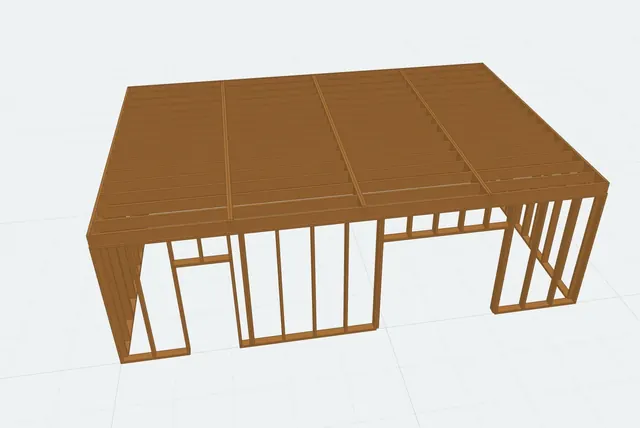
If your shop also builds in steel, the same joint logic applies: Stud's guide to wall panelization in light gauge steel shows where to split steel walls, and light gauge steel vs timber frame panels compares what changes between the two for a prefab builder.
Open or closed panels?
The layout rules are the same for both, but the panel type changes the weight, and so the maximum width you can lift.
- Open panels: frame, racking board and often a breather membrane. Insulation, vapour control layer and linings go in on site. Lighter, and the frame stays visible for inspection and services.
- Closed panels: insulation, vapour control layer and sometimes linings, windows and service runs fitted in the factory. More work done under cover, but a heavier panel to lift and protect in transit.
Whichever you build, work out the weight of a panel before fixing its width: timber volume × density, as in the timber frame wall take-off, plus boards and whatever else goes in at the factory.
How do you set the maximum panel width?
The maximum panel width isn't a trade constant: it's a setting that belongs to your factory and your transport. Two neighbouring manufacturers can use different values, and the same firm can lower it for a site with tight access. List your limits and take the smallest:
| Limit | What it caps | Where to get the figure |
|---|---|---|
| Factory table | Panel length and width, built flat | Your table or line dimensions |
| Overhead crane, site crane | Panel weight and lifting points | The machine's load chart, at the actual radius |
| Lorry (truck) | Wall height (panels flat) or panel width (panels upright), and loaded weight | Your haulier: trailer, A-frames, road limits |
| Site | Access, storage, crane radius | Site visit, site set-up plan |
| Stud spacing | Widths that keep the stud grid regular | Your standard build-up (and your engineer) |
For road limits, don't go from memory: check them with your haulier for the way they load. Whether panels travel flat or upright changes which panel dimension matters.
Then pick a maximum width that's a multiple of your stud spacing: 3.00 m is 5 × 600 mm, 2.40 m is 4 × 600 mm or 6 × 400 mm. At 3.00 m with 400 mm centres (7.5 spaces), joints no longer land on the grid and every panel ends with a short bay. If you work in feet, the same applies on a 16 or 24 in. grid: 8 ft is 6 × 16 in. or 4 × 24 in.
Where should the joints between panels go?
A panel joint is two end studs, one per panel, fixed together on site. The rules for placing them:
- never through an opening, and not right against its edge: between the opening and the joint you need room for the full-height studs and cripple studs (king and jack studs in the US), plus the panel's end stud;
- on the stud grid where you can, so the end stud replaces a common stud instead of adding one;
- at corners, decide which wall runs through (it carries the corner) and which butts into it, and keep that rule across the whole job. The butting wall is shorter by the thickness of the through wall;
- at internal wall junctions, decide whether the internal wall fixes to a panel or lands on a joint, and put the junction studs in the right panel;
- under the top plate: if your system fits the head binder (the second top plate) on site, stagger its joints from the panel joints so it ties the panels together;
- avoid narrow panels when you have the choice: a 1.20 m panel takes as much handling and fixing as a 3.00 m one. Moving two joints beats creating a small panel, though the example below shows it isn't always possible.
The method, wall by wall:
- List the openings in the wall, with their position in metres from the starting corner.
- Divide the wall length by the maximum width, rounded up: that's the minimum number of panels.
- Place the joints at regular spacing, then check each one against the openings.
- Move every joint that lands in an opening to the nearest stud clear of the opening and its trimmers, without exceeding the maximum width. Moving one joint often pushes the next: work from left to right.
- Check corners, internal wall junctions and narrow panels, then write down each panel's width. They must add up to the wall length.
- Number the panels (see below).
Large openings and gables: when the rule breaks
The first check before you split a wall: the largest opening, plus its trimmers and an end stud each side, must fit within the maximum panel width. If it doesn't, no layout can respect both the maximum width and "no joint through an opening". You have to choose:
- a wider panel for that wall, if the table, the crane and the lorry allow it. Often the simplest answer for a single large opening;
- an opening formed on site: the panels stop either side, and the lintel or beam (often glulam or LVL) is fitted during erection. Bearings, fixings and the lintel section are for your structural engineer;
- a higher maximum width for the whole job, if several walls have the same problem.
Gables raise the other question: height. Above the first floor or the top plates, the triangle is built either as a separate gable panel (a spandrel panel in the UK) set on the wall panels, or with raked-top panels. The limiting dimension is no longer width but height, on the table and on the lorry.
Short piers between openings are the third case: a pier too narrow to take a joint forces the joint further along, sometimes at the cost of a shorter panel elsewhere. The example below shows all three reflexes: check the large opening, move the joints, accept a narrower panel.
Numbering panels and planning the erection sequence
Once the joints are fixed, each panel gets a unique mark, shown on the layout drawing, on the production sheet and on the panel itself. A simple convention, kept from one job to the next:
- the level (GF, FF in the UK; level 1, level 2 in the US);
- the elevation or wall (by orientation, or W1, W2… in take-off order);
- the panel number, left to right seen from outside: P1, P2, P3…
Erection usually starts from a corner, through wall first, then the panels in sequence. Loading runs the other way: the first panel to go up is the last one loaded, so it comes off the lorry first. Mark the orientation on every sheet too (outside face, top of panel): a symmetrical panel fitted the wrong way round puts an opening in the wrong place.
Example: a 12 m elevation in 3.00 m panels, then 2.40 m panels
Elevation 12.00 × 2.50 m, studs at 600 mm centres. Openings, in metres from the left-hand corner: window from 1.00 to 2.20; window from 4.20 to 5.40; door from 7.00 to 7.90; glazed opening from 9.40 to 11.80 (2.40 m wide). Example values to show the method: replace them with those from your plan, your factory and your haulier.
With a maximum width of 3.00 m. 12.00 / 3.00 = 4 panels. The regular joints fall at 3.00, 6.00 and 9.00 m. Checked against the openings:
- 3.00 m: 0.80 m after the first window, 1.20 m before the second;
- 6.00 m: 0.60 m after the second window, 1.00 m before the door;
- 9.00 m: 1.10 m after the door, 0.40 m before the glazed opening.
No joint through an opening, and all on the grid (5, 10 and 15 spaces of 600 mm). Each panel carries one opening: P1 the first window, P2 the second, P3 the door, P4 the glazed opening, with 0.40 m on the left and 0.20 m on the right for its trimmers.
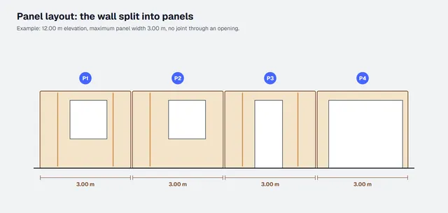
With a maximum width of 2.40 m. Your lorry or crane limits you to 2.40 m. 12.00 / 2.40 = exactly 5 panels, so the joints are forced to 2.40, 4.80, 7.20 and 9.60 m:
- 2.40 m: 0.20 m after the first window, which works;
- 4.80 m: through the second window (4.20 to 5.40);
- 7.20 m: through the door (7.00 to 7.90);
- 9.60 m: through the glazed opening (9.40 to 11.80).
Three joints out of four have to move, and since five 2.40 m panels make exactly 12.00 m, none can move without adding a panel. Start again from the left. The 4.80 m joint moves back to 3.60 m: the stud at 4.20 m is the window edge, so it can't take a joint. P2 is now only 1.20 m wide. P3 runs from 3.60 to 6.00 m (2.40 m, second window in the middle), P4 from 6.00 to 8.40 m (2.40 m, the door with 0.50 m to spare on the right).
That leaves 3.60 m, from 8.40 to 12.00 m, with a 2.40 m glazed opening. It takes the whole maximum width on its own, with no room for its trimmers: no 2.40 m panel can hold it. That's the case from the previous section.
| Maximum width | Panels | Joints (m from the left) | Joints through an opening |
|---|---|---|---|
| 3.00 m, regular split | 4 | 3.00 · 6.00 · 9.00 | none |
| 2.40 m, regular split | 5 | 2.40 · 4.80 · 7.20 · 9.60 | 3 (window, door, glazed opening) |
| 2.40 m, joints moved | 6 or more | 2.40 · 3.60 · 6.00 · 8.40, then the glazed opening | the glazed opening has no answer |
The takeaway: going from 3.00 to 2.40 m doesn't cost one panel but at least two (P2 at 1.20 m, and the remaining 3.60 m that won't fit in one), moves three joints out of four and runs into the glazed opening. For this elevation there are two ways out: keep the 3.00 m layout if the crane and the lorry can take it on this job, or form the glazed opening on site with a lintel fitted during erection. Both are decided with the factory and the engineer, before you draw the frame.
Racking board layout: 1.25 m boards and offcuts
Once the wall panels are fixed, lay out the racking boards panel by panel, not along the whole wall: in the factory, each wall panel gets its own sheathing, which stops at the joint. Every board edge must be fixed to a framing member (stud, plate or nogging); sections, fixings and board type are checked against your design code (Eurocode 5, EN 1995, in the UK and Europe; the IRC for US homes) with your engineer.
With 2.50 × 1.25 m racking boards fitted vertically on the example elevation (four 3.00 m wall panels, 2.50 m high):
- 3.00 / 1.25 = 2.4: per wall panel, 2 full boards and one 0.50 m strip;
- 4 wall panels: 8 full boards and 4 strips of 0.50 m;
- the 4 strips come out of 2 boards (0.50 + 0.50, 0.25 m offcut): 10 racking boards, 31.25 m² for 30.00 m² of gross elevation, so 1.25 m² of offcuts (about 4%).
Over the whole wall with no panel joints, 12.00 / 1.25 = 9.6 also gave 10 boards, but with one cut strip instead of four. The wall panel layout doesn't always change the number of boards; it changes the number of cuts and the size of the offcuts. With a wall panel width that's a multiple of 1.25 m (2.50 m, 3.75 m), the boards would fit exactly.
Watch the grid as well: 1.25 m isn't a multiple of 600 mm. At 600 mm centres, the edges of 1.25 m boards miss the common studs, so add a stud or batten at each board joint, or use a board width that follows your stud spacing (1.20 m boards on 600 mm centres, 4 ft sheets on 16 or 24 in. centres). Openings are then cut out of the boards, and their offcuts rarely make a full-height strip. Turning these areas into quantities is covered in the timber frame wall take-off, and where they sit in the price in how to price a timber frame house from plans.
Frequently asked questions
What width should timber frame wall panels be?
Whatever your weakest link allows: factory table, lifting, transport or site. Make it a multiple of your stud spacing, and check that it's wider than your largest opening plus its trimmers.
Can a panel joint go through a window or door opening?
Not in a standard layout: the lintel and the trimmers belong in one panel. An opening wider than the maximum panel width is formed on site with a lintel fitted during erection, designed by your engineer.
Does the panel layout change the take-off?
Yes. Each joint adds an end stud (two studs where a continuous wall would have one), and it changes the racking board cuts. Do the panel layout before the final take-off.
What is the maximum width for transporting a wall panel?
It depends on how the panels are loaded (flat or upright) and on the vehicle. Check the limits with your haulier before you set your maximum panel width.
Doing it with Stud, from the plan you receive
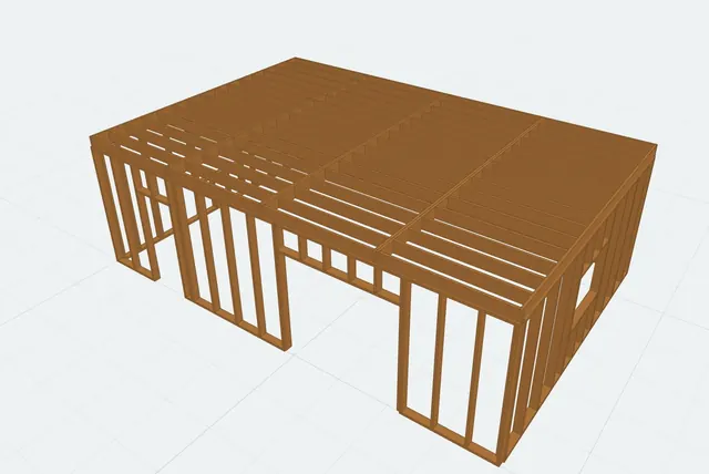
Stud is an AI agent that builds the building from the plan, then splits its walls into panels when you ask:
- you upload a DXF or PDF plan, a plan image or a dimensioned sketch; the agent builds the building in 3D and, when a dimension is missing, uses a standard value and flags it for you;
- in the project settings, you set "Max panel width (mm)" and "Stud spacing (mm)": your factory and transport limits;
- you ask it to split the walls into panels: it does, and draws the frame of each panel (studs, plates, lintels), step by step in the 3D view;
- you select a panel or a wall in the 3D view and type the change; if you change the maximum width, "Apply and rebuild" rebuilds the frame.
Check the joint positions, especially around large openings: Stud doesn't do structural design or code checks. Exports (IFC, production PDFs with one sheet per panel, machine files) come with the Framer plan; the free beta does everything in the app, without exports.
200 free credits, no card required. Try it on an elevation you've already laid out and compare the joint positions.
Related guides
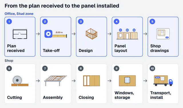 Timber frame prefabrication workshop: the workflow from plan to delivered panelTen steps, who does what with which tool, and where a shop loses hours between the plan and the panel.
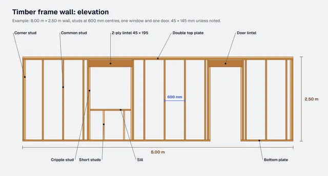 Timber frame glossary: 68 English-French termsThe vocabulary of walls, sheathing, floors, take-off and drawings, in UK English, US English and French, with the false friends.
 Timber frame estimating and design software: what to use at each stageSpreadsheets, timber CAD/CAM, PDF takeoff tools and AI agents, sorted by stage, with a comparison table and a worked example in hours.