Timber frame panel shop drawings: what each panel drawing must show
In short
A timber frame panel shop drawing is the sheet the shop builds one panel from: a front view with every stud, plate, noggin, lintel and board located and dimensioned, the panel's mark and orientation, and its own parts list. The shop's technical office or a detailer draws it from the panel layout and the engineer's design, and a second person checks it before anything is cut. If a joiner has to phone to know where a piece goes, the drawing isn't finished.
The architect's plans show the building and the engineer's drawings show what carries the load. Neither tells the table operator where the fourteenth stud of panel six goes. The panel shop drawing does, and it is the document that decides whether the panel comes off the table right. Here is what it must contain, who produces it, how to check it, and the drawing of one real panel from an 8 m wall.
What is a timber frame panel shop drawing?
A shop drawing (also called a panel drawing or fabrication drawing) is the sheet the shop builds from. It describes one panel, or one group of identical panels with a quantity: its outline, every member inside it, what goes on it and how it is marked. Everything on the sheet is decided. Nobody has to measure, interpret or call the office.
It sits in a chain with a clear order. The panel layout comes before it and fixes the panel widths and the joint positions. The shop drawing then fixes everything inside each panel. From the drawing come the cutting list for the saw and the parts list for the table, and the sum of all panels must agree with the wall take-off.
Light gauge steel shops have the same sheet under the name panel detailing: light gauge steel panel detailing from 2D plans shows how the steel version is built.
What must a panel shop drawing show?
The core is a front view of the panel, seen from the outside face, drawn to scale. Every row of the table below belongs on it.
| Element | What the drawing shows | What goes wrong without it |
|---|---|---|
| Outline | Panel width and height, taken from the panel layout, with the start point at the left end seen from outside | Panel built to the wall length instead of the panel width |
| Studs | Position of every stud along the panel, section and cut length (height minus plates); common studs, end studs at joints, corner studs | Stud grid shifted at a joint, short bay not noticed |
| Plates | Bottom plate (cut at doors), first ply of the top plate and its length; second ply (head binder) fitted on site, dashed, with its joints staggered from the panel joints | Plate runs through a door; plate joints land on panel joints |
| Openings | Rough opening width, head height and sill height from the floor, with the full-height (king) studs and the jack studs | Opening cut to the window frame size instead of the rough opening |
| Lintels | Section, number of plies, length and bearing on the jack studs | Lintel cut short, or bearing on a short stud |
| Sill and short studs | Sill length, short studs under the sill and their positions | Missing support under a window board |
| Noggings (blocking) | Rows, height, section and position | A board or lining edge with nothing behind it |
| Sheathing (racking board) | Board layout, joints on framing, edge fixing lines, and whether it is fixed on the table | Board edge in the middle of a bay |
| Marks | Panel mark, then a mark for each kind of piece | Pieces from two panels mixed on the table |
| Parts list | Each piece: mark, section, length, quantity; panel weight | The cutting list and the drawing disagree |
Three drafting habits make the sheet usable at the table:
- dimension from one end (running dimensions), never chain dimensions: the operator reads each position straight off the sheet, with no addition. Openings are dimensioned from the left end of the panel to the rough opening edge, plus head and sill heights;
- show sections and fixings as notes tied to the engineer's design: the draughtsperson doesn't choose them, the drawing carries them (stud section, plate section, board type, fixing pattern);
- keep the sheet to one panel: a drawing that covers a whole elevation hides the joint between panels, where most errors are made.
How do you mark and orient the panels?
Every panel has a unique mark that appears on the layout, on its sheet and on the panel itself. A convention that works from one job to the next: wall, then panel in order, left to right seen from outside, for example W1-P1, W1-P2. Add the level in front (GF, FF in the UK; level 1, level 2 in the US) when the job has several.
Then give each type of piece a short code: ST for studs, JK for jack studs, SL for sills, SS for short studs, BP for bottom plates, TP for top plates, HB for head binders, LT for lintels. The same codes appear on the parts list, on the cutting list and on the pieces if you label them.
Orientation takes three lines on the sheet and prevents the most expensive mistake: a symmetrical panel fitted the wrong way round puts an opening in the wrong place. Show an arrow to the outside face, mark the top of the panel, and state which neighbour sits on its left and on its right. The panel layout guide covers the numbering sequence and the erection order.
Who produces the shop drawings?
In most timber frame shops, the technical office (or a detailer working for the shop) draws them. The inputs are the architect's plans, the engineer's design, the panel layout and the shop's own rules: stud spacing, plate build-up, how openings are trimmed. The outputs are the sheets, the cutting list and the machine or table instructions.
The split of responsibility is simple:
- the engineer sets sections, spacing, fixings and bracing, and signs off what carries load;
- the shop decides how to build it: panel widths, joints, build order, what is fitted on the table;
- the drawing is where both meet, and the shop is accountable for it matching what was designed.
How do you check a panel drawing before it goes to the table?
A second person checks every sheet before release, with a fixed list, and the sheet gets a revision letter. The list:
- Panel width and joints match the panel layout, and the panel widths add up to the wall length.
- Stud length equals the wall height minus the plates, for the plate build-up the sheet states.
- Every opening matches the window and door schedule as a rough opening, not as a frame size, with head and sill heights from the floor.
- Each opening is complete: two king studs, two jack studs, a lintel, and for a window a sill and short studs under it.
- Spacing is regular where it should be, and every board edge and lining edge lands on a stud, plate or nogging.
- Marks are unique and the orientation is shown.
- The parts list adds up: count the pieces on the view and compare them with the list, then compare the timber volume of all the panels with the take-off.
- Revision and date are on the sheet, and the previous revision is withdrawn from the shop.
Step 7 catches most of the silent errors. If the panels of a wall add up to the continuous wall plus one end stud per joint, the drawings are consistent with the take-off. If not, one of the two is wrong, and you want to know before the saw runs.
Example: the drawing of one panel from an 8 m wall
Wall W1 of 8.00 × 2.50 m, studs 45 × 145 at 600 mm centres, one bottom plate and a double top plate, lintels in 2 plies of 45 × 195 (the wall of the take-off guide), split into two panels at 4.20 m, the seventh space of 600 mm. Panel W1-P1 runs from 0 to 4.20 m and holds a window of 1.20 × 1.25 m, sill at 0.95 m, head at 2.20 m, from 2.00 to 3.20 m. Example values to show the method: replace them with those from your plan and your build-up.
The sheet for W1-P1 shows the view below, with its title block and parts list.
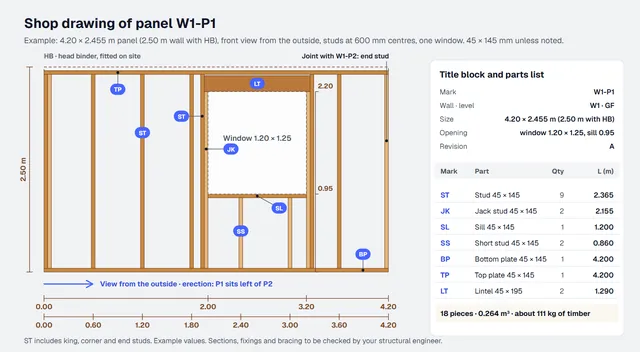
How the 18 pieces of the panel come out:
- 9 studs of 2.365 m: the end stud and the corner stud at the left end, 3 common studs at 0.60, 1.20 and 1.80 m, one at 3.60 m, 2 king studs for the window, and the end stud at the joint (2.50 − 3 × 0.045 = 2.365 m);
- 2 jack studs of 2.155 m, under the lintel (2.20 − 0.045);
- 1 sill of 1.20 m and 2 short studs of 0.86 m under it (0.95 − 2 × 0.045), at 2.40 and 3.00 m;
- 1 bottom plate of 4.20 m and 1 top plate of 4.20 m, the first ply (the second ply, the head binder, is fitted on site with its joints staggered from the panel joints: it is not on the panel sheet but in the wall binder pieces);
- 2 lintels of 1.29 m in 45 × 195 (1.20 + 2 × 0.045).
Four dimensions place the window: 2.00 and 3.20 m from the left end, 0.95 m for the sill, 2.20 m for the head.
The parts list gives 36.915 m of 45 × 145 and 2.58 m of 45 × 195: 0.264 m³ of timber, about 111 kg (C24 at 420 kg/m³, the density used in the take-off guide), before boards and anything fitted on the table. Panel W1-P2 adds 34.66 m of 45 × 145 and 1.98 m of 45 × 195. Together: 71.575 m, plus the 8.00 m of head binder of the wall (3.00 + 3.00 + 2.00 m, fitted on site): 79.575 m, which is the 77.21 m of the continuous wall in the take-off guide plus one end stud of 2.365 m for the joint. The full cutting list of this wall is in the timber frame cutting list guide.
Frequently asked questions
Who draws timber frame shop drawings?
The shop's technical office, or a detailer working for it. The engineer provides the design (sections, spacing, fixings, bracing), the architect provides the plans, and the shop turns them into sheets it can build from.
How many drawings does a timber frame job need?
One per panel, or one per group of identical panels with a quantity. When panels repeat, the job needs fewer sheets than panels, each sheet carrying its quantity, plus the layout drawing that links them.
Does the shop drawing replace the engineer's drawings?
No. The engineer's drawings and calculations set what the structure must be. The shop drawing shows how the shop builds it, panel by panel. The two must agree, which is the point of the check before release.
What is the difference between a panel drawing and a cutting list?
The drawing shows where each piece goes. The cutting list is the same pieces sorted for the saw, by section and length. Both come from the same data, and the cutting list guide shows how to build it.
Doing it with Stud: model, panels, framing and panel sheets
Stud is an AI agent, in free beta, that builds the model and the panels from the plan you already have and draws the framing:
- you upload a DXF or PDF plan, a plan image or a dimensioned sketch; the agent builds the 3D model and uses a standard value, flagged for you, for a dimension it is missing;
- you set the maximum panel width and the stud spacing in the project settings; the agent splits the walls into panels and draws the framing of each one (studs, plates, lintels), step by step in the 3D view;
- you click a panel or a member in the 3D view and type the change you want: you edit the model, and the panel follows;
- with the Framer plan, the production PDFs give the framing plan of each level and one sheet per panel.
Check each sheet against the list in this guide before it goes to the table. Stud doesn't do structural design or code checks: sections, fixings and bracing stay with your engineer. The free beta does everything in the app, without exports.
Free beta: sign up and try it on one of your own plans, then compare the panel sheets with the ones you draw today.
Related guides
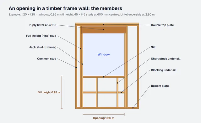 Timber frame window opening: lintel, jack studs and sill in a wallKing and jack studs, lintel, sill, short studs and blocking: how to count and cut them, with a worked example.
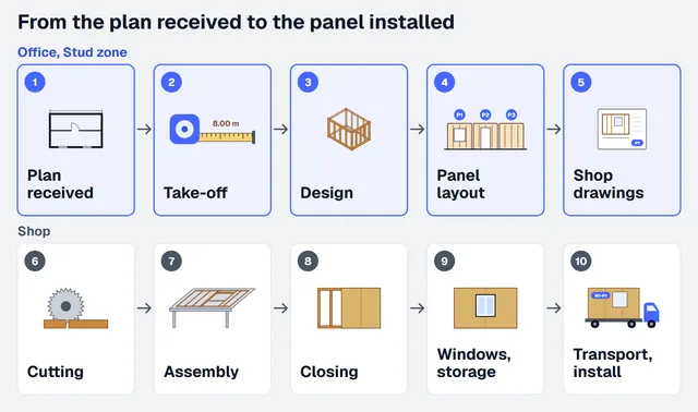 Timber frame prefabrication workshop: the workflow from plan to delivered panelTen steps, who does what with which tool, and where a shop loses hours between the plan and the panel.
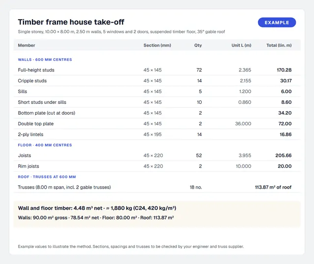 Timber frame take-off from a 2D plan: walls, studs and roof trussesWalls, floor joists and roof trusses, counted from one plan. Worked example on a 10 × 8 m house.