DXF, PDF or image: which plan to use (and prepare) for a timber frame take-off
In short
DXF and PDF are the two file formats a timber frame take-off usually starts from: a DXF is CAD geometry drawn full size and sorted into layers, a PDF is a vector export or a scan of the drawings. Use the DXF when there is one, but check its units against a known dimension. A vector PDF can be measured too, as long as you set the scale from a written dimension, not the title block; a scan, a plan image or a sketch only gives you the dimensions written on it. Either way, list what's missing (heights, sill heights, wall thicknesses, load-bearing walls) and ask for it before you price.
A timber frame take-off starts with a file: a DXF exported by the architect, a PDF of the planning drawings, sometimes a scan or a dimensioned sketch from the client. These formats don't carry the same information, and they don't mislead you in the same way. This guide compares what each one lets you measure, shows how to prepare the plan before you count a single stud, and lists what to ask the architect.
What does a DXF, a PDF or a plan image actually contain?
Faced with any file, ask three questions: can the geometry be measured? Is the scale or unit known? Are the dimensions you need written on it? The three formats answer them differently.
DXF: full-size geometry
DXF is a CAD exchange format that most drafting software can write and read. It holds the vector geometry of the plan: lines, polylines, arcs, blocks (doors, windows) and text, sorted into layers (walls, partitions, windows and doors, dimensions, furniture, hatching). The drawing is usually made full size, so you measure distances directly, without a scale.
Two things to check before you trust it:
- Units. A DXF can declare its unit in the file header (the INSUNITS variable), but many files don't, or declare a value that doesn't match the drawing. The same 12 m wall can read 12, 1,200 or 12,000 depending on whether it was drawn in metres, centimetres or millimetres; on a US drawing in inches, a 40 ft wall reads 480. Measure a known dimension first.
- Dimensions. They can be true dimension objects, whose text is normally worked out from the geometry but may have been overridden by hand, or plain lines and text. If the written figure and the measured distance disagree, that's a question to ask, not a value to pick.
Other common traps: the whole drawing on a single layer, furniture and walls mixed together, several floors, elevations and sections laid side by side in the same drawing, or externally referenced parts that didn't travel with the file.
PDF: vector or scanned
A PDF exported from the architect's software is usually vector: lines stay sharp at any zoom, and a PDF measuring tool can measure them once the scale is set. The original layers may have been kept or flattened on export.
A PDF can also be just a scan: an image wrapped in a PDF, with all the limits of an image. To tell, zoom right in on a line: a vector line stays sharp, a scan turns to pixels.
Above all, the scale in the title block (1:100, 1:50, or 1/4 in. = 1 ft on a US set) only holds for the original sheet size. An A3 drawing printed on A4 with "fit to page", or an 11×17 sheet printed on Letter, or a cropped PDF, is no longer at the stated scale.
Plan image, scan, dimensioned sketch: only what's written
A plan image (PNG, JPG), a scan or a hand-drawn dimensioned sketch carries no geometry you can measure reliably: unknown or rough scale, thick lines, a skewed scan, a sketch that isn't to scale. What counts is the written dimensions. A missing dimension stays missing: measuring it with a ruler on an image gives you an order of magnitude, not a cutting dimension.
How do you read architectural drawings for a timber frame take-off?
Architectural drawings describe rooms; a framing take-off needs a building you can make. Whatever the format, you need to be able to read:
- the outside face of the walls, or enough to get back to it: if dimensions are internal or to centrelines, you need the wall thickness to bring them out to the outside of the frame;
- wall thicknesses and the build-up: where the frame sits in the drawn thickness (external insulation, service void, linings);
- heights: overall wall height per storey and floor zone depth; the ceiling height isn't enough;
- openings: position, width, height and sill height of every window, door and glazed opening;
- levels: number of storeys, floor levels, any split levels;
- internal walls: position, and above all which ones are load-bearing.
What planning drawings rarely show
Drawings made for planning approval, or an early design set, are produced for the planning officer, not the shop floor. They show the footprint, floor areas and what the elevations look like, but rarely dimensioned sill and lintel heights, the wall build-up, which walls are load-bearing, floor span directions or detailed levels. Across a set of drawings, heights come from the section, sill heights from the elevations, widths and positions from the floor plan. Anything dimensioned nowhere becomes a question. That's step 1 of our method to price a timber frame house from plans.
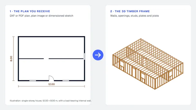
DXF vs PDF: which is better for a take-off?
| Format | What you can measure | Traps | Use it for |
|---|---|---|---|
| DXF | All the geometry, full size; wall lengths, opening positions | Units missing or wrong; messy layers; dimension text overridden; several floors in one drawing | The take-off, once units are checked and layers sorted |
| Vector PDF | Lines, with a measuring tool, once the scale is set | Title-block scale wrong after printing or cropping; layers sometimes flattened | The take-off when there's no DXF; checking dimensions |
| Scanned PDF, plan image | The written dimensions; the rest as an order of magnitude | Skewed or stretched scan; thick lines; unknown scale | A first estimate, then a list of questions |
| Dimensioned sketch | The written dimensions, and nothing else | Not to scale; incomplete dimension strings | Small jobs and extensions, as long as everything is dimensioned |
In practice: ask for the DXF as soon as the job looks real, keep the PDF as the record of what the client approved, and never measure a dimension that could be written. If the architect works in DWG, ask for a DXF export of each floor.
How do you prepare a plan before the take-off?
Ten minutes of preparation saves you taking off a wrong plan. In order:
- Check the revision. Note the plan's revision and date. A take-off done on an out-of-date plan is wrong, however careful.
- Check the scale or units against a known dimension. Take the longest written dimension (the front elevation), measure it and compare. Do it in both directions: a scan can be stretched one way.
- Isolate the layers you need (DXF): walls, partitions, windows and doors, dimensions. Hide furniture, hatching, room labels and fit-out dimensions.
- Crop to one floor at a time. Separate ground floor, first floor, elevations and sections, even if they sit in the same file.
- Check the dimension strings: the running dimensions along an elevation must add up to the overall dimension.
- Note the kind of dimensions (internal, external, to centrelines) and bring everything back to the outside face of the frame.
- List the missing dimensions and the questions for the client. For each gap, write the question and the assumption you'll use if the answer doesn't come.
What you get from this is a readable plan and a list of questions. Counting studs, plates and opening framing comes next, and it's covered in our timber frame wall take-off guide.
Example: checking the scale of a printed PDF
The figures below are example values to show the calculation: replace them with the dimensions and measurements from your own plan. The case: a floor plan stated at 1:100 on an A3 sheet, which you printed on A4.
The known dimension. The front elevation is dimensioned 12.00 m. At 1:100 it should measure 120 mm on paper. You measure 85 mm with a scale rule.
The real scale. 12,000 mm / 85 mm = 141.2. The printed plan is at about 1:141, not 1:100. That's the ratio between A3 and A4: 297 / 420 = 0.707, and 120 × 0.707 = 84.9 mm.
The check in the other direction. The gable is dimensioned 8.00 m; you measure 56.5 mm. 8,000 / 56.5 = 141.6. Both directions agree, within the accuracy of the rule: the print is scaled down, not distorted. If you found 1:141 one way and 1:150 the other, the image would be stretched: don't measure anything, ask for the DXF.
What a scale error costs. An undimensioned pier between two windows measures 30 mm on the print. Read at 1:100: 3.00 m. At 1:141.2: 30 × 141.2 = 4,236 mm, so 4.24 m. That's 1.24 m out on a single wall.
Reading accuracy. At 1:141, half a millimetre on the rule is 0.5 × 141.2 = 71 mm, about 7 cm on site. Fine for an order of magnitude, not for cutting a stud: the pier width is still a question for the architect.
The same applies to imperial sets: an 11×17 sheet at 1/4 in. = 1 ft printed on Letter with "fit to page" is no longer at 1/4 in. = 1 ft. Work out the real scale from a known dimension in the same way.
What should you ask the architect before pricing?
Put the questions in one message, numbered, each with the assumption you'll use if there's no answer. Ask for:
- the DXF of each floor, matching the PDF revision, stating the drawing unit;
- a dimensioned section: floor levels, floor zone depth, wall heights;
- dimensioned elevations or the window and door schedule: width, height and sill height of every opening;
- the intended wall build-up, or at least the overall thickness and what it includes;
- the load-bearing walls and floor span directions, or the structural engineer's contact;
- the plan revision, so you know which version you're pricing and what will change next.
Sections, stud spacing and racking aren't for the architect to give you: they're your shop's choices, checked by your engineer against the applicable rules (Eurocode 5 in Europe, the IRC for US homes).
Frequently asked questions
Can you do a take-off from PDF plans?
Yes, if the PDF is vector and you set the scale from a written dimension rather than the title block. For a scanned PDF, use only the written dimensions and ask about the rest.
How do you find the real scale of a printed plan?
Measure the longest written dimension, divide the real dimension by the measured length, then repeat in the other direction. If both results agree, the print has only been scaled up or down.
My DXF shows 12000 for a 12 m wall. Is that normal?
Yes: the drawing is in millimetres. It's common, which is why you check the unit against a known dimension instead of relying on what the file declares.
Do I need to redraw the plan before the take-off?
No. Prepare it: sort the layers, crop by floor, check the scale and list the missing dimensions. Redrawing the whole project takes time on a job you haven't won yet. If you need a model, see how a DXF, a PDF or a plan image goes from floor plan to 3D model.
Doing it with Stud, from the plan you receive
Stud is an AI agent that starts from the plan you've prepared and builds the model from it:
- you attach the plan to your message in the chat: a DXF or PDF, a plan image (PNG, JPG, WEBP) or a dimensioned sketch;
- for a DXF, you pick the layers you need and crop to the part to work on; the files stay attached to the project;
- the agent builds the building in 3D; when a dimension is missing (wall height, sill height, thickness), it uses a standard value and flags it for you;
- the take-off comes from the model: wall, floor and roof areas, timber volume and weight.
Clean, well-dimensioned plans give the best results, so the preparation above still pays off. Stud doesn't calculate prices and doesn't do structural design.
200 free credits, no card required. Attach the DXF or PDF of a job you've already taken off and compare.
Related guides
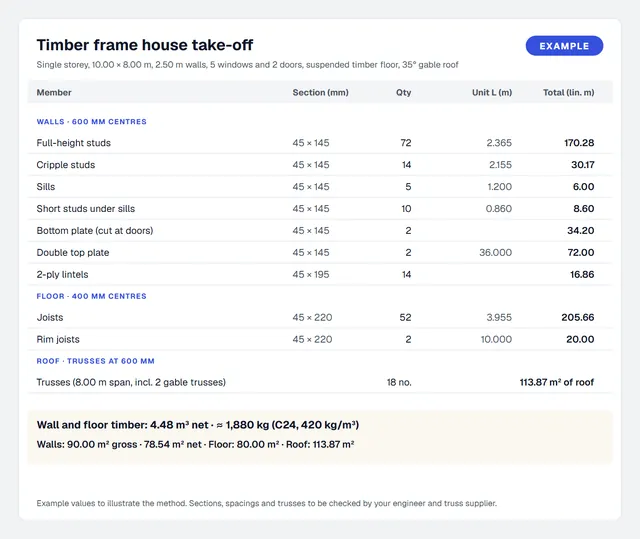 Timber frame take-off from a 2D plan: walls, studs and roof trussesWalls, floor joists and roof trusses, counted from one plan. Worked example on a 10 × 8 m house.
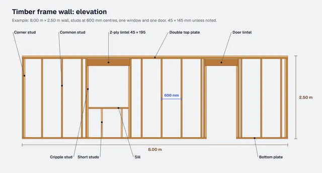 Timber frame glossary: 68 English-French termsThe vocabulary of walls, sheathing, floors, take-off and drawings, in UK English, US English and French, with the false friends.
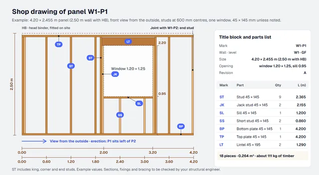 Timber frame panel shop drawings: what each panel drawing must showStuds, plates, noggings, lintels, marks, dimensions and parts list, how to check a drawing, and one panel worked in full.